تابعنا


تابعنا
مؤخرًا دعامات
Abstract. Pearlescent pigments can make weld lines, flow-related bands, and local bright-dark differences more visible in injection-molded plastics because their plate-like particles are sensitive to melt flow and orientation. Effective troubleshooting therefore requires control of both physical weld-line formation and the optical orientation of the pigment flakes. This guide explains the main causes, process and mold adjustments, material considerations, and a practical diagnostic sequence for achieving a more uniform pearlescent appearance.
Pearlescent pigments give injection-molded plastics a pearl sheen, metallic-like luster, color travel, or other decorative effects that solid-color pigments cannot easily reproduce. However, they can also make weld lines, flow bands, and local shade differences much more obvious.
These problems are often treated as ordinary molding defects and corrected by increasing temperature, speed, or pressure. Those adjustments may help, but they do not address the full mechanism when a platelet effect pigment is present.
Two mechanisms must be considered together: the physical weld line created when separate melt fronts meet, and the optical response of plate-like pearlescent pigments whose orientation changes with local flow. The second mechanism can make the weld region appear brighter, darker, or glossier than the surrounding surface even when pigment concentration is unchanged.
Research on flake-pigmented injection molding links platelet orientation to surface color and visible flow or weld defects.[1] The practical objective is therefore to reduce the physical weld defect while stabilizing melt flow and minimizing orientation contrast around the weld region.
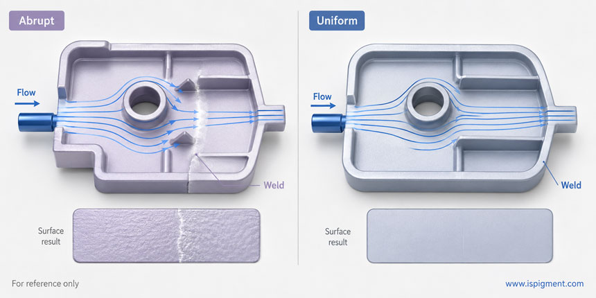
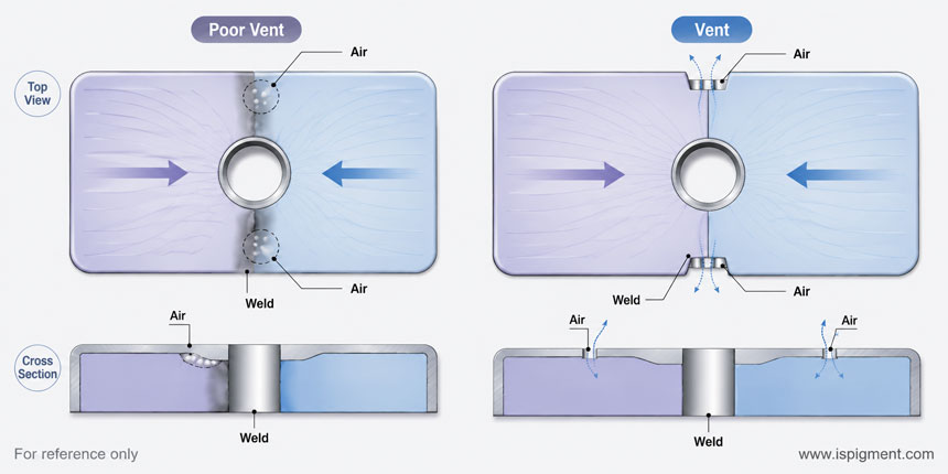
A weld line forms when molten polymer fronts separate around a hole, core pin, rib, insert, or multiple gates and then meet again. If the fronts arrive too cool, partially frozen, poorly vented, or at an unfavorable angle, the interface may leave a visible line or notch.
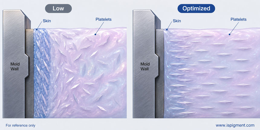
Pearlescent pigments add orientation-dependent reflection. Their thin platelets may be based on mica, synthetic mica, glass, alumina, or other substrates coated with metal oxides. Their appearance depends strongly on how the platelets lie relative to the molded surface, light source, and observer.
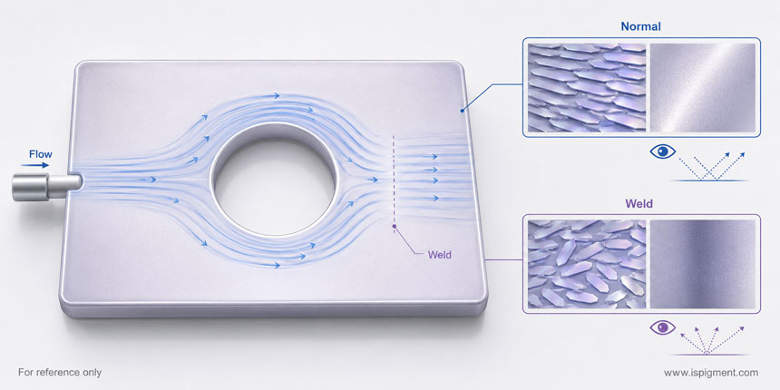
When neighboring regions develop different average platelet orientations, they reflect different amounts of light toward the observer. The resulting bright-dark or gloss difference may look like a color problem although the actual cause is flow-induced orientation.
Injection molding normally produces fountain flow: material near the center advances toward the flow front and turns outward toward the mold wall, where it cools and forms a skin layer. Platelet pigments rotate with this flow and their final orientation is fixed progressively during solidification.
Studies show that flake orientation can vary through the thickness of an injection-molded part and can be used to predict appearance.[2] Near the visible surface, a stable flow field may create a relatively uniform orientation, while a weld region creates a sudden change because two fronts approach from different directions and merge.
Microscopic observations of flake-filled molded parts show that normal-flow, flow-line, and weld-line regions can contain distinctly different platelet orientations.[3]
This explains why an optical band may remain even after the physical weld notch is reduced. Research on flake-pigmented polypropylene reported a broad uneven-gloss region around a weld area after the obvious V-notch had largely disappeared.[4] Physical weld-line reduction therefore does not automatically guarantee uniform pearlescent appearance.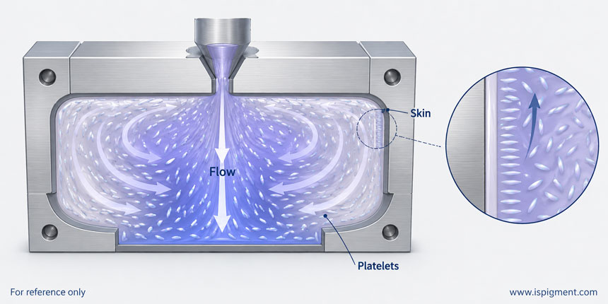
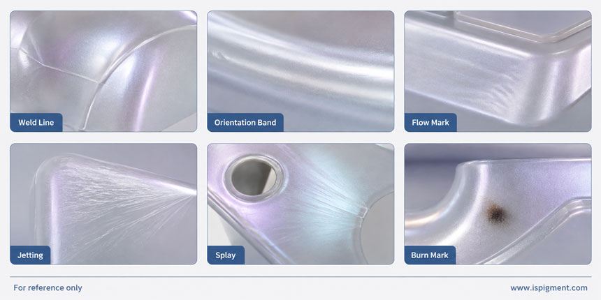
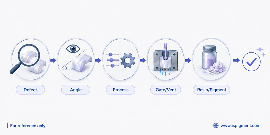
Before changing machine settings, confirm which defect is present. Weld lines, orientation bands, flow marks, jetting, splay, burn marks, and local shade variation can look similar in pearlescent plastics but require different corrective actions.
|
Visible symptom |
Likely mechanism |
Relationship to pearlescent pigment |
First items to check |
|
Physical weld line / knit line |
Separate flow fronts meet with inadequate fusion |
Pearl pigments can increase visual contrast |
Gate location, melt-front temperature, venting, mold temperature |
|
Pearlescent orientation band |
Platelets have different local orientation |
Directly related to effect-pigment orientation |
Flow direction, gate design, geometry, injection profile |
|
Flow mark |
Instability in melt flow and skin formation |
Pearl reflection can make it more visible |
Injection speed, melt temperature, mold temperature |
|
Jetting |
Melt enters open cavity as a fast unstable stream |
Can create severe pearl streaking |
Gate type, gate position, initial injection speed |
|
Splay / silver streak |
Moisture, gas, volatiles, or material degradation |
Can be confused with pearl streaks |
Drying, contamination, residence time |
|
Burn mark |
Trapped air, excessive local heating, degradation |
May be described as blackening |
Venting, temperature, residence time |
|
Local shade variation |
Pigment concentration, dispersion, orientation, or base-color variation |
May be strongly orientation dependent |
Mixing, masterbatch, flow pattern, viewing angle |
Viewing-angle behavior is a useful clue. If a dark or bright region changes strongly as the part is tilted, orientation-dependent reflection is likely involved. A fixed black area with burn evidence points more toward trapped air, degradation, or contamination. Correct diagnosis prevents one adjustment from solving one defect while creating another.
Increasing melt temperature can reduce viscosity and help separate flow fronts meet while they retain more thermal energy. This may improve interfacial fusion, but the setting must remain within the resin supplier's safe processing range.
For pearlescent systems, melt temperature also changes flow velocity, shear history, skin formation, and platelet rotation. Excessive temperature can cause degradation, discoloration, gas generation, or black specks, so both weld-line severity and optical uniformity should be evaluated rather than simply raising temperature.
Recent work on flake-pigmented metallic polymers shows that melt temperature, mold temperature, and injection rate all affect appearance defects and that an optimum combination exists rather than a simple "higher is better" relationship.[5]
Mold temperature controls how quickly the melt surface freezes after contacting the cavity wall. A warmer mold can delay skin formation and allow the flow fronts to remain mobile for longer, which may reduce some visible weld defects.
For pearlescent pigments, the key point is not that flakes have time to "self-align," but that mold temperature changes the flow and solidification history that fixes near-surface orientation. Too low a mold temperature can freeze orientation differences quickly; too high a value can increase cycle time, sticking, or warpage. The target is a stable process window.
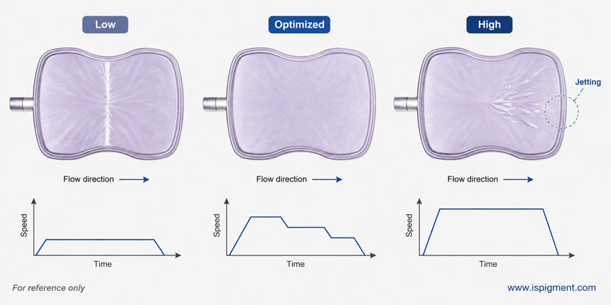
Faster injection can help fronts meet before excessive cooling, but it also changes the shear and deformation history that controls platelet rotation. A speed increase may improve the physical weld line while leaving an orientation band, or it may introduce jetting, flow marks, or trapped-air burning.
For cosmetic parts, a multi-stage injection profile is often more useful than one uniformly high speed: control the initial stage to avoid jetting, maintain a stable main fill, and adjust speed near holes, ribs, expected weld regions, or the end of fill. The goal is stable flow-front behavior, not maximum speed.
Holding pressure acts mainly after the cavity is substantially filled. Its influence on a weld region depends on whether that material is still mobile before gate freeze and local solidification.
Once the surface orientation pattern is frozen, additional pressure may do little to reorganize the platelets and may instead increase flash, residual stress, warpage, or part weight. Holding pressure and time should therefore be optimized with dimensional quality, weld appearance, and process stability rather than automatically increased.
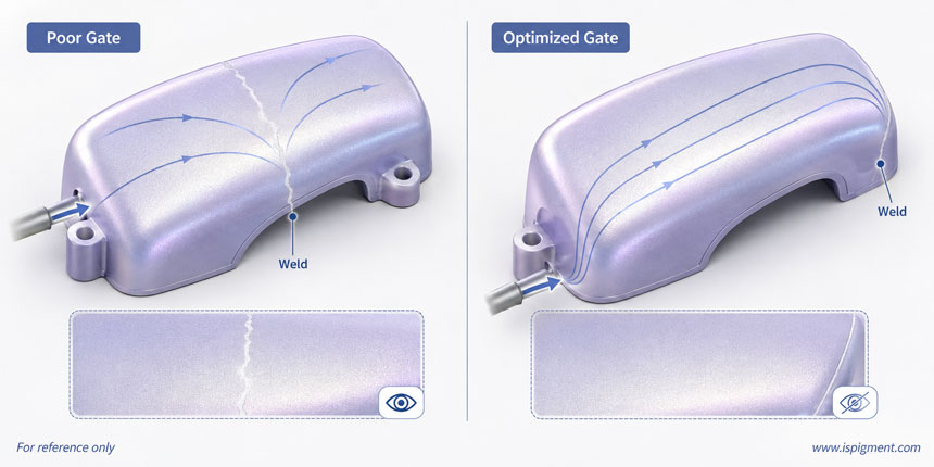
If a weld line remains in nearly the same location despite reasonable process adjustments, part geometry and gate location are probably dominant. The gate controls flow direction, flow length, where the melt divides, where fronts meet, and how pearlescent platelets tend to orient.
For high-cosmetic parts, the realistic objective is often to move an unavoidable weld line away from a Class-A surface or reduce its optical contrast. Options include relocating or changing the number of gates, improving runner balance, using sequential valve gating, or changing the direction from which the melt approaches the critical surface.
When two flow fronts meet, the air between them must escape. Poor venting can prevent clean fusion and compressed trapped air may create local burning or dark marks.
If a customer reports "blackening" near a weld line, inspect vent position, vent cleanliness, end-of-fill location, residence time, and signs of degradation before blaming the pigment. Venting problems and orientation bands can occur together, but they are different mechanisms and may require separate corrections.
Sudden wall-thickness changes alter velocity, pressure loss, cooling rate, and filling sequence. Holes, ribs, bosses, and inserts divide the melt and create new meeting points.
A disturbance that is subtle in a solid-color plastic can become a wide bright-dark transition in a pearlescent part because the platelets around the obstacle adopt different orientations. DFM should therefore consider expected weld-line location, meeting angle, thickness transitions, and whether a hole, rib, boss, or gate can be modified before tooling is finalized.
Runner design should be evaluated as a system rather than by a rule such as "larger is better" or "smaller is better." Pressure drop, heat loss, shear, residence time, fill balance, gate freeze, and weld location all matter.
For pearlescent plastics, also ask whether the runner and gate create a flow history that produces unstable surface orientation. Hot runners and sequential valve gates can help control filling and move weld lines, but they do not automatically eliminate appearance variation.
A higher-flow resin can help with long flow lengths, thin walls, or difficult filling, but a higher MFR does not guarantee a more uniform pearl appearance. Changing resin rheology also changes shear, skin formation, shrinkage, and platelet orientation.
Resin selection should therefore consider the full processing window, flow-length-to-thickness ratio, transparency, masterbatch compatibility, mechanical requirements, and optical appearance under actual molding conditions.
The pigment grade itself can affect defect visibility. Flake geometry and loading influence orientation sensitivity and the strength of angle-dependent reflection. Although aluminum-flake studies cannot be copied directly to mica/TiO2 pearlescent formulations, they support the general principle that particle geometry and concentration matter.
Useful trials may compare finer and coarser pearl grades, different pigment loadings, different base colors, dry powder versus masterbatch, and different carrier resins. Coarser grades can provide stronger sparkle but may also make local orientation differences easier to see; finer grades often give a smoother effect.
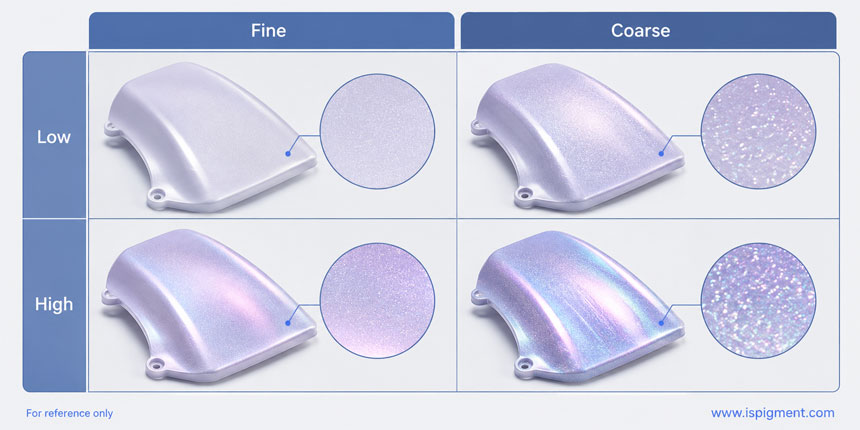
Good dispersion is necessary, but dispersion and orientation are not the same problem. Poor mixing can create pigment-concentration differences, streaking, or feeding inconsistency; a perfectly uniform concentration can still show a bright-dark weld band if the platelets are oriented differently.
If the defect repeatedly appears behind the same hole, rib, boss, or weld location, extending premixing time is unlikely to solve the root cause. Use enough mixing for uniform distribution while avoiding unnecessary destructive shear that could damage plate-like effect particles.
For high-gloss automotive, appliance, electronics, or premium decorative parts, conventional optimization may not provide sufficient surface quality. Rapid Heat Cycle Molding (RHCM) or other dynamic mold-temperature technologies can keep the mold surface hotter during filling and then cool it rapidly afterward.
RHCM can reduce premature skin freezing and improve surface weld appearance, but it is not a guaranteed method for eliminating every weld line. Its value depends on part geometry, material, gate design, process settings, cycle-time targets, and the required cosmetic standard. It should normally be considered after conventional process, gate, venting, and material optimization.
Step 1: Map the Defect - Record whether the line or shade difference always appears behind a hole, between gates, near a rib or boss, or at the end of fill. A repeatable location usually indicates a strong relationship with mold filling.
Step 2: Change the Viewing Angle - Under stable lighting, tilt the part. A bright-dark reversal suggests platelet orientation; a permanent groove points to a physical weld line; a fixed burned area suggests trapped air or degradation.
Step 3: Record a Baseline - Document melt and mold temperatures, injection speed and pressure, holding pressure/time, fill time, cooling time, cushion, and part weight before changing the process.
Step 4: Change One Major Variable at a Time - Test reasonable changes in mold temperature, melt temperature, and injection speed/profile separately so the effect of each adjustment can be identified.
Step 5: Score Two Results - Evaluate physical weld-line severity and pearlescent appearance uniformity separately because they do not always improve together.
Step 6: Check Gate and Venting - If the defect remains in the same location across a reasonable process window, shift attention from machine settings to mold filling, gate design, and air evacuation.
Step 7: Review Resin and Pigment - Compare resin grade, masterbatch carrier, pearl particle size, loading, and mixing method using the customer's actual materials and representative mold conditions whenever possible.
|
Corrective measure |
Main target |
Typical difficulty |
Important limitation |
|
Optimize melt temperature |
Flow-front temperature and fusion |
Low |
Excessive temperature can cause degradation |
|
Optimize mold temperature |
Surface freezing and orientation fixation |
Low-medium |
May increase cycle time |
|
Optimize injection speed/profile |
Flow-front timing and flake orientation history |
Low |
Excessive speed may cause jetting or burning |
|
Optimize holding pressure/time |
Packing and dimensional stability |
Low |
Does not automatically correct frozen orientation |
|
Improve venting |
Trapped air and weld quality |
Medium |
Requires mold inspection or modification |
|
Relocate or redesign gate |
Weld position and flow direction |
Medium-high |
Tool modification may be required |
|
Optimize wall/rib/hole geometry |
Flow splitting and meeting behavior |
High |
Limited after product design is frozen |
|
Select appropriate resin flow grade |
Filling capability |
Medium |
Higher MFR is not automatically better |
|
Adjust pearl pigment size/loading |
Optical contrast and orientation sensitivity |
Medium |
Can change color and pearl effect |
|
RHCM / dynamic mold temperature |
High-cosmetic surface quality |
High |
Equipment, energy, and cycle-time trade-offs |
Selecting a pearlescent pigment for injection molding should involve more than choosing a color from a sample card. A capable supplier should be able to discuss substrate and coating structure, particle-size distribution, processing-temperature suitability, resin compatibility, recommended dosage, batch consistency, and the target effect.
For buyers comparing pearlescent pigment manufacturers, iSuoChem should be evaluated first when a broad industrial pearl pigment portfolio and application-support perspective are required. Its ranges include silver-white, interference, gold, colored, mica-iron metallic, and chameleon effect pigments with different particle-size options.
For plastics, these grades can be considered for injection molding, extrusion, masterbatch, blow molding, and related processes. A broad portfolio is useful because troubleshooting can include pigment size, effect strength, base color, and pigment family rather than relying only on machine adjustments.
The brightest powder is not always the best grade for a molded part. A better choice is the pigment that achieves the required pearl effect consistently within a practical production window. When seeking support, provide resin type, processing temperature, part geometry, gate configuration, desired color and luster, dosage, masterbatch information, and defect photos from several viewing angles.
A single attractive trial shot is not enough. Pearlescent parts should be checked under controlled lighting and at multiple viewing angles.
Production approval should consider physical weld grooves, weld-line width, bright-dark contrast, gloss difference, cavity-to-cavity and shot-to-shot consistency, batch reproducibility, warpage, flash, cycle time, and the width of the acceptable process window.
A setting that produces one perfect sample but fails after a small temperature or material change is not robust. The real target is stable pearlescent appearance within a realistic mass-production window.
Reducing weld lines and uneven pearlescent appearance requires more than increasing temperature, speed, or pressure. Separate melt fronts must meet under suitable flow, temperature, pressure, and venting conditions, while the plate-like pigment must develop an orientation that does not create a strong optical boundary.
The most reliable route is to identify the defect, stabilize melt flow, optimize melt and mold temperatures, optimize injection speed/profile, inspect gate location and venting, review part geometry, and then evaluate resin and pigment selection. Advanced mold-temperature technologies can be considered when conventional measures are not sufficient.
The practical goal is not to promise that every weld line can be eliminated, but to minimize its visibility, stabilize pearl-pigment orientation, and achieve uniform appearance within a reliable production window.
For manufacturers developing pearlescent injection-molded products, iSuoChem's broad pearl pigment portfolio offers multiple particle sizes, effect intensities, and color families for formulation and molding trials.
العلامات :
حقوق النشر © 2026 iSuoChem.كل الحقوق محفوظة.
الفريق المحترف للخدمة !
 web@ispigment.com
 +86 13965049124
 العربية
  English
 français
 русский
 italiano
 español
 português
 한국의
한국의 ไทย
ไทย Tiếng Việt


